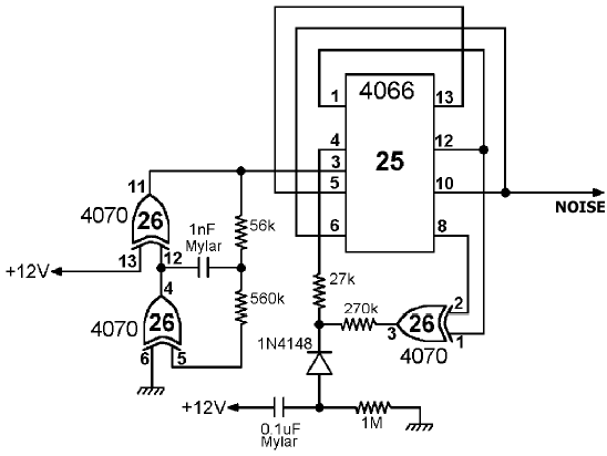
Noise generator, used by the trigger and flash circuits.

This circuit implements a linear feedback shift register that provide a pseudorandom source of binary digits (in analog form). Pin 3 must be connected to a clock source that in this case is implemented by a CMOS oscillator.
It took me a long search to get a document that explains exactly how these things work, but eventually I found a very interesting reference in the Application Note 118 by Fairchild Semiconductor (October 1974) named "CMOS oscillators". While the document deals only with inverting gates, it explicitly states that any CMOS gate or combination of gates can be used and gives a formula to get an approximate frequency for the above configuration:
f = 1 / (2 C (0.405 Req + 0.693 R1))
where
Req = R1 R2 / (R1 + R2)
In the picture above R1=56Kohm, R2=560Kohm and C=1nF. This yields a frequency of about 8400 Hz which I tried to used directly into the flash circuit but it is too high. (However, if I manually tune the frequency with the help of the predigitized sample then the flash circuit is emulated almost completely. What's left is the duration of the one-shot impulse, which causes the noise to fade out while the corresponding port bit is still active. In other words, if "red screen" is enabled then it lasts slightly longer than the sound effect.)
Copyright (c) 2004 Alessandro Scotti. All rights reserved.
| Home :: Computer Programming :: Space Invaders soundboard |